Gas burner
My Dacre Gas Burner

Construction
The Parts
The picture below shows the main burner parts as made. at the bottom is the actual burner tube.
The top row Left to Right are:
For the actual gas jet I obtained a commercially made one as I didn't fancy drilling a hole as small as 0.15 mm (0.06 inch) on the equipment I have. It would probably cost me more in materials and broken drills than the commercial one.
I constructed the gas burner as per the drawing derived from the CAD set I found on the internet. The first items I made were the body, air regulator and gas jet holder. These were relatively simple turning jobs on the lathe. The cross holes in the main body were drilled on my milling machine using a rotary table mounted vertically with a 3 jaw chuck to hold the work. Unfortunately I forgot to photograph the process but it was relatively straightforward. The holes for the 2 mm grub screws (US = 'set screws', in the UK a set screw is a machine screw with threads along the complete length of the shank as opposed to a bolt which only has a portion of the shank threaded) were drilled and then tapped at the same stage to ensure alignment.
Assembly
Once the parts were machined, the gas tube, tube cap and main body were assembled and silver soldered (aka 'brazed' in the US). I used typists correction fluid painted on close to and around the joints as a resist to prevent excess solder spreading. After soldering a cooling a little the assembly was pickled in Citric acid for around 30 minutes, the residue scrubbed off and the parts cleaned with
abrasive. I only apply the minimum of silver solder so there was very little excess to clean off.
As a heat source I use two different torches, on is a standard torch as used by plumbers eta with disposable cylinders of butane/propane gas mix - I used this to solder the burner body. With larger assemblies such as boilers, I use a larger Sievert torch which uses propane from large refillable cylinders at pressures of up to 4 bar (approx. 60 psi for our US friends). There are of course other makes available but I find Sievert to be the best quality - that is just an opinion, if you are buying shop around and handle a few makes.
I intend to buy a smaller burner nozzle for my Sievert torch to replace my 'plumbers' torch simply due to cost. At the time of writing a 336 gm disposable canister of gas for the latter costs around £5.00 while a 13 kg cylinder of propane costs around £23.00. To get 13 kg gas in disposable canisters I would need around 39 at a cost of nearly £200. It's not really that simple as the larger torch obviouly consumes a much higher volume of gas but there is stil a very significant cost saving. My basic Sievert torch package, with body, neck, burner and hose cost around £55.00 from a local tool supplier and a 4 bar regulator was around £13.00 direct from from Flogas (UK gas supplier - including shipping at the time).
Cutting Burner Slots

One of the issues I was facing was how to cut consistently accurate 1 mm wide slots as per the drawing. In order to do this either manually or by machining \i would need some kind of 'jig' or 'fixture' to aid accuracy and consistency. For a definition of these terms see the Jigs and Fixtures page.
I first thought of using a hacksaw with a jig to guide the blade. This would need two slots to guide the blade and a hole through to hold the gas tube steady, perhaps with a locking screw. Then I would need a method to ensure the tube didn't rotate, this would perhaps consist of a slot to guide a loose pin through the air holes in the body. It would only need two saw guide slots,as the tube would be aligned in the jig for the first cut with the hacksaw guided by the slot to a fixed depth, the tube would then be slid along so the cut aligned with the second slot and a thin, 1 mm piece of sheet would position it while the second slot cut.was made, the tube then moved along located by the thin sheet in the second slot and then the third cut made and so on until all 13 were cut.
I saw several problems with this, the jig would have to be steel, probably hardened to prevent the cutting guide slot getting deeper, but this meant that this would damage the hacksaw blade so perhaps hardened rollers would be the answer. Then to prevent any problem of possible twisting of the tube while cutting there needs to be a guide and then possibly a locking screw - this was getting very complex, but some designers, especially those with fixed ideas. I prefer simplicity, I have a simple mind, so it was back to the (virtual) drawing board.
The next idea was similar but using a 1 mm slitting saw mounted on an arbor in the lathe spindle. A jig or fixture could be mounted on the slotted cross slide, however on the Boxford there is no simple way to move the cross slide along the lathe accurately to set dimensions. So a jig similar to the one described above could be used but again this involves complications.

Construction
 |
| Finished Burner minus Mounting Bracket |
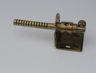
The Parts
The picture below shows the main burner parts as made. at the bottom is the actual burner tube.
The top row Left to Right are:
- Gland screw,
- Gas jet holder,
- Air regulator sleeve
- Main body, ad
- Gas tube end cap.
 |
| Parts as Made for Gas Burner Before Assembly |
I constructed the gas burner as per the drawing derived from the CAD set I found on the internet. The first items I made were the body, air regulator and gas jet holder. These were relatively simple turning jobs on the lathe. The cross holes in the main body were drilled on my milling machine using a rotary table mounted vertically with a 3 jaw chuck to hold the work. Unfortunately I forgot to photograph the process but it was relatively straightforward. The holes for the 2 mm grub screws (US = 'set screws', in the UK a set screw is a machine screw with threads along the complete length of the shank as opposed to a bolt which only has a portion of the shank threaded) were drilled and then tapped at the same stage to ensure alignment.
 |
| Test Assembly to Prove Fitting |
Assembly
Once the parts were machined, the gas tube, tube cap and main body were assembled and silver soldered (aka 'brazed' in the US). I used typists correction fluid painted on close to and around the joints as a resist to prevent excess solder spreading. After soldering a cooling a little the assembly was pickled in Citric acid for around 30 minutes, the residue scrubbed off and the parts cleaned with
abrasive. I only apply the minimum of silver solder so there was very little excess to clean off.
 |
| Burner Soldered and Cleaned |
 |
| Sievert Pro 86 Torch Kit with 4 bar Gas Pressure regulator. |
I intend to buy a smaller burner nozzle for my Sievert torch to replace my 'plumbers' torch simply due to cost. At the time of writing a 336 gm disposable canister of gas for the latter costs around £5.00 while a 13 kg cylinder of propane costs around £23.00. To get 13 kg gas in disposable canisters I would need around 39 at a cost of nearly £200. It's not really that simple as the larger torch obviouly consumes a much higher volume of gas but there is stil a very significant cost saving. My basic Sievert torch package, with body, neck, burner and hose cost around £55.00 from a local tool supplier and a 4 bar regulator was around £13.00 direct from from Flogas (UK gas supplier - including shipping at the time).
Cutting Burner Slots

One of the issues I was facing was how to cut consistently accurate 1 mm wide slots as per the drawing. In order to do this either manually or by machining \i would need some kind of 'jig' or 'fixture' to aid accuracy and consistency. For a definition of these terms see the Jigs and Fixtures page.
I first thought of using a hacksaw with a jig to guide the blade. This would need two slots to guide the blade and a hole through to hold the gas tube steady, perhaps with a locking screw. Then I would need a method to ensure the tube didn't rotate, this would perhaps consist of a slot to guide a loose pin through the air holes in the body. It would only need two saw guide slots,as the tube would be aligned in the jig for the first cut with the hacksaw guided by the slot to a fixed depth, the tube would then be slid along so the cut aligned with the second slot and a thin, 1 mm piece of sheet would position it while the second slot cut.was made, the tube then moved along located by the thin sheet in the second slot and then the third cut made and so on until all 13 were cut.
I saw several problems with this, the jig would have to be steel, probably hardened to prevent the cutting guide slot getting deeper, but this meant that this would damage the hacksaw blade so perhaps hardened rollers would be the answer. Then to prevent any problem of possible twisting of the tube while cutting there needs to be a guide and then possibly a locking screw - this was getting very complex, but some designers, especially those with fixed ideas. I prefer simplicity, I have a simple mind, so it was back to the (virtual) drawing board.
The next idea was similar but using a 1 mm slitting saw mounted on an arbor in the lathe spindle. A jig or fixture could be mounted on the slotted cross slide, however on the Boxford there is no simple way to move the cross slide along the lathe accurately to set dimensions. So a jig similar to the one described above could be used but again this involves complications.
Comments
Post a Comment