Cylinders
The original Dacre used commercially available cylinders but I decided to make my own from scratch. They are made from brass bar of a suitable size using basic techniques on the lathe, milling machine and the bench.
 |
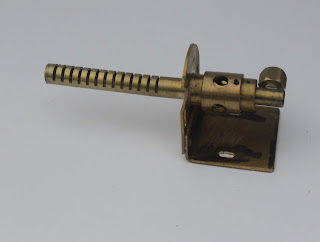
| Dacre Cylinder and Valve Gear Assembly |
I used a length of 32 mm (actually 1 1/4") square brass which I cut down to within 0.5 mm to final width in both dimensions using a slitting saw, this gives me some brass strip cutoffs rather than the brass swarf if I used an end mill. I bought it to final size of 25 mm x 26.5 mm with an end mill and gave it a final finish with abrasive cloth which was flat on a surface plate.
 |
| Cylinder profile |
The end of the bar was coated with a permanent marker so that layout lines are easily visible. and the centre of the main cylinder bore marked. This is important as most of the other profile dimensions are based around this centre, this centre was then defined accurately with a punch. The profile was then marked out with dividers and scriber. The reverse curve was simply marked around a suitable sized washer.
Unfortunately I lost many of the photographs of the manufacturing process so I will just have to explain with text. The brass block was made long enough that both cylinders could be made from one blank. This was mounted in the 4 jaw chuck with the bore centred and drilled to within 1mm of final size with a number of drills increasing in size from an initial 8 mm drill following the use of a slocomb centre drill. The final size was cut with an h7 14 mm reamer and then honed with emery cloth held in a split holder in the tailstock chuck. The hone was passed back and forth quickly with the chuck rotating slowly thus giving a fine cross hatching which helps to hold lubricant and reduce wear.
 |
| Cylinder Blank with Layout, Drilled, Reamed and Honed |
Machining The Blank
Once the blank was bored the majority of the surplus brass was machined away on the milling machine with the blank held in the vice and rotated as needed. To achieve the final shape the blank was held on a mandrel in the lathe and a side oriented tool was used in the toolpost to 'plane' away the brass to the final profile by moving the saddle back and forth taking a fine shaving at a time and rotating the blank slightly by hand the final shape was achieved.
 |
| Cylinders Roughed to Shape on Milling Machine - Note Visible Face at Bottom |
The two cylinders were now made by cutting the blank in half and facing to length in the 4 jaw chuck on the lathe. The ports and mounting holes were marked out and drilled and the steam passages completed with a 2mm milling cutter.
The end caps were a plain turning exercise using the 3 jaw chuck and parting off. Each was then reversed in the chuck and the locating shoulder turned to 14 mm to locate the end caps in the cylinder bore. The valve chest was machined from solid to the dimensions given.
Test Installation
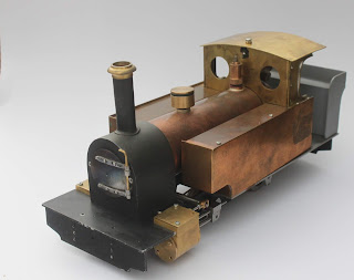
I have made a test installation of the cylinders onto the Frames to check fit.
 |
| Test Installation of Cylinders |


Comments
Post a Comment