Frames
My DIY Dacre
Frames.
The frames consist of:
The first parts I tackled were the actual side frames. The blanks were cut from 2.5 mm sheet as a couple of strips. The material I had available was rusted on one side and painted on the other so after cutting some cleaning up was necessary. First I stripped the paint with stripper and abrasive cloth, and then the cut blanks were immersed in citric acid for a couple of hours after removing loose rust with wire brush and abrasive cloth.
The blanks were then glued together with Cyanoacrylate superglue and machined. First to width and then to length, in the milling machine. They were then coated with marking black - permanent felt tip (Sharpie) actually - and then marked out as accurately as possible with my equipment. The side frames were then machined and drilled, they were then separated by heating gently until the superglue failed.
The most crucial dimension is perhaps the wheelbase as the coupling rods have to be drilled to the same dimension to prevent them locking. I actually drilled the axle holes at 2 mm initially which meant that I could use the side frames as a jig to drill the coupling rods.
So at this point I altered my build sequence and cut some coupling rod blanks. I then drilled the crank pin hole at one end, then bolted the rod to the side frame using this hole. Aligning the other end I used the side frame as a jig to drill the second hole in the coupling rods ensuring accuracy - or so I thought - see later..
Stretcher Bars

I then cut the stretcher bars from 6 mm square steel bar and machined them all to length at the same time in the milling machine in order to ensure consistent length. holes were then marked on individual stretcher as required and was then a simple drilling job. The fixing holes in the end were drilled using the 4 jaw chuck in the lathe and then tapped while in the chuck using the tap in a hand chuck aligned using the tailstock holder. The chuck was locked and the tap turned by hand.
Buffer Support Plates
The buffer beam spacers (Buffer Support Plates above) were cut from steel bar and milled to shape on the milling machine, then drilled and tapped. The rivet holes were not drilled as I intended to use the buffer beams as a drilling jig, however I drilled the central buffer fixing hole in both the support and the buffer beams so that I could bolt them together to ensure accuracy when drilling the rivet holes - I also used cyanoacrylate superglue to fix the buffer beams to the support beams to help when drilling rivet holes.
Buffer Beams
Buffer beams were cut and drilled from the same sheet that I cut the side frames from. The shaping and drilling was relatively straightforward but drilling accuracy was quite important as the rivets are very visible and inaccuracy really stands out.
Axle Bearing Bushes
The final parts to be made were the phosphor bronze axle bushes. These were a simple turning job. The bar was first faced, centre drilled and step drilled to within 0.5 mm of final bore. The final reaming to size was done after assembly in order to ensure alignment of the axle holes. The 'top hat' profile was first turned on the end of a 12 mm bronze round bar then parted off oversize to allow for final facing of the outer face to size later.
Assembly of Frames
The first job was to silver solder the axle bearing bushes in to the side frames. This was done after cleaning up the parts to be fixed and fluxing with 'Easy-Flo' flux. The assembled sides and bushes were then heated on my simple brazing hearth and silver solder applied to each bush in turn.
The Frame stretchers were bolted to the side frames using hexagon head set screws (the term 'set screw' is used in the USA to describe what we in the UK call 'grub screws'). I use metric fasteners and these have the classification for the set screw stamped on to the head. In order to make these look more authentic I turned the head of each screw in the lathe to remove the classification stampings. Once the structure was loosely bolted together I attached the buffer beam support plates to each end. This was then weighted down on a surface plate - unfortunately I have no pictures - with large blocks of steel while I tightened the set screws progressively in order to keep the structure flat and prevent twist. This completed the basic frame.
The buffer beams were bolted in place with superglue used to hold the beam in place. The rivet holes were drilled and the rivets inserted and peened in situ. The outer round head of the rivet was supported in a rivet 'set' while the inner part of the rivet was peened into the countersunk hole.
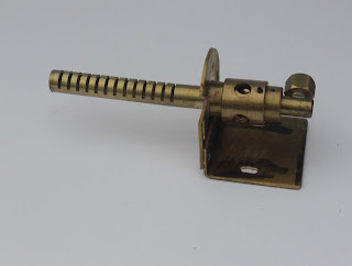
***Insert picture of rivet set here***
A rivet set can be made from a cheap woodworking nail punch. Cheap because they are usually not hardened and are are available in a variety of sizes to suit a range of rivets. I modify them by drilling the end with a twist drill of the diameter of the rivet head to the depth of the grinding angles of the drill. A ball bearing of a suitable size is placed in the 'dimple' while the punch is supported vertically in the vice. The while wearing safety goggles the bb is then struck firmly with a heavy hammer to create a smooth concave dimple which will support the round rivet head. No hardening is usually necessary as most rivets we use are soft iron, copper or brass
Frames.
The frames consist of:
- side frames,
- cross members,
- buffer beam supports,
- buffer beam, and
- axle bushes (main bearings).
 |
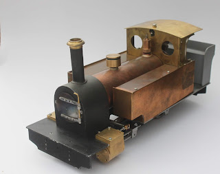
| View of assembled frames with Cylinder, wheels and running gear. |
Side Plates
The first parts I tackled were the actual side frames. The blanks were cut from 2.5 mm sheet as a couple of strips. The material I had available was rusted on one side and painted on the other so after cutting some cleaning up was necessary. First I stripped the paint with stripper and abrasive cloth, and then the cut blanks were immersed in citric acid for a couple of hours after removing loose rust with wire brush and abrasive cloth.
 |
| Frame side plates. |
The blanks were then glued together with Cyanoacrylate superglue and machined. First to width and then to length, in the milling machine. They were then coated with marking black - permanent felt tip (Sharpie) actually - and then marked out as accurately as possible with my equipment. The side frames were then machined and drilled, they were then separated by heating gently until the superglue failed.
 |
| Side Frame Blanks From Reclaimed Steel |
 |
| Completed Side Frames. |
The most crucial dimension is perhaps the wheelbase as the coupling rods have to be drilled to the same dimension to prevent them locking. I actually drilled the axle holes at 2 mm initially which meant that I could use the side frames as a jig to drill the coupling rods.
So at this point I altered my build sequence and cut some coupling rod blanks. I then drilled the crank pin hole at one end, then bolted the rod to the side frame using this hole. Aligning the other end I used the side frame as a jig to drill the second hole in the coupling rods ensuring accuracy - or so I thought - see later..
Stretcher Bars

I then cut the stretcher bars from 6 mm square steel bar and machined them all to length at the same time in the milling machine in order to ensure consistent length. holes were then marked on individual stretcher as required and was then a simple drilling job. The fixing holes in the end were drilled using the 4 jaw chuck in the lathe and then tapped while in the chuck using the tap in a hand chuck aligned using the tailstock holder. The chuck was locked and the tap turned by hand.
Buffer Support Plates
 |
| Buffer support plates |
The buffer beam spacers (Buffer Support Plates above) were cut from steel bar and milled to shape on the milling machine, then drilled and tapped. The rivet holes were not drilled as I intended to use the buffer beams as a drilling jig, however I drilled the central buffer fixing hole in both the support and the buffer beams so that I could bolt them together to ensure accuracy when drilling the rivet holes - I also used cyanoacrylate superglue to fix the buffer beams to the support beams to help when drilling rivet holes.
 |
| Stretcher Bars (R) and Buffer Beam Support Stretcher (L) |
Buffer Beams
Buffer beams were cut and drilled from the same sheet that I cut the side frames from. The shaping and drilling was relatively straightforward but drilling accuracy was quite important as the rivets are very visible and inaccuracy really stands out.
 |
| Buffer Beams |
The final parts to be made were the phosphor bronze axle bushes. These were a simple turning job. The bar was first faced, centre drilled and step drilled to within 0.5 mm of final bore. The final reaming to size was done after assembly in order to ensure alignment of the axle holes. The 'top hat' profile was first turned on the end of a 12 mm bronze round bar then parted off oversize to allow for final facing of the outer face to size later.
 |
| Axle Main Bearings (L) and Wheels |
Assembly of Frames
The first job was to silver solder the axle bearing bushes in to the side frames. This was done after cleaning up the parts to be fixed and fluxing with 'Easy-Flo' flux. The assembled sides and bushes were then heated on my simple brazing hearth and silver solder applied to each bush in turn.
The Frame stretchers were bolted to the side frames using hexagon head set screws (the term 'set screw' is used in the USA to describe what we in the UK call 'grub screws'). I use metric fasteners and these have the classification for the set screw stamped on to the head. In order to make these look more authentic I turned the head of each screw in the lathe to remove the classification stampings. Once the structure was loosely bolted together I attached the buffer beam support plates to each end. This was then weighted down on a surface plate - unfortunately I have no pictures - with large blocks of steel while I tightened the set screws progressively in order to keep the structure flat and prevent twist. This completed the basic frame.
The buffer beams were bolted in place with superglue used to hold the beam in place. The rivet holes were drilled and the rivets inserted and peened in situ. The outer round head of the rivet was supported in a rivet 'set' while the inner part of the rivet was peened into the countersunk hole.
***Insert picture of rivet set here***
A rivet set can be made from a cheap woodworking nail punch. Cheap because they are usually not hardened and are are available in a variety of sizes to suit a range of rivets. I modify them by drilling the end with a twist drill of the diameter of the rivet head to the depth of the grinding angles of the drill. A ball bearing of a suitable size is placed in the 'dimple' while the punch is supported vertically in the vice. The while wearing safety goggles the bb is then struck firmly with a heavy hammer to create a smooth concave dimple which will support the round rivet head. No hardening is usually necessary as most rivets we use are soft iron, copper or brass
 |
| Assembled Frames (With Other Components) |

Comments
Post a Comment